Ever struggled to fit a component into a PCB hole that's just a bit too tight—or too loose? Choosing the right hole size for through-hole pins isn't just guesswork—it's critical to performance and reliability.
In this post, you'll learn how to select the optimal PCB hole size using proven rules, IPC standards, and real-world tips. We'll also explore how precision tools like CNC drilling machines ensure perfect results every time.
Introduction: Why PCB Hole Size Selection Matters
Getting the hole size right on a PCB sounds simple, but it's a small detail that makes a big impact. Through-hole components need precise holes to sit properly, and even the tiniest mismatch can throw everything off. If the hole is too tight, the pins won't fit without bending or forcing. If it's too loose, components wobble or shift, making it harder for solder to flow and stick. That means weaker joints, more rework, and in the worst case, a board that just doesn't work.
Think about how solder flows around a pin. It needs a little space to move, but not too much. This space—called clearance—helps the solder flow properly and grab onto both the pin and the pad. But if you ignore it, solder may not stick well or form voids, especially when using lead-free solder. Problems like cold joints, incomplete connections, or even cracked pads can show up later.
Manufacturing adds its own challenges too. Drilled holes always vary slightly in size, and when copper plating is added, the final hole diameter shrinks. So, even if the drill was right, the finished hole might still be off. That's why designers must plan ahead and build in tolerances to match both the pin size and the drilling method. A little over or under, and you risk insertion failures on the assembly line, driving up costs and delays.
It all comes down to precision. Every board, every component, every hole must work together smoothly. And that starts by understanding how important hole size really is.
Understanding Through-Hole PCB Design Basics
Through-hole technology has been around for decades, and it's still widely used in electronics manufacturing today. Instead of placing components on the surface like with SMT, this method involves inserting component leads into pre-drilled holes in the board. Those leads stick out the other side and are soldered in place, giving a strong and secure connection. You'll often find through-hole parts in products where durability matters, such as power supplies, transformers, or anything used in tough environments.
There are two main types of holes you'll see in this kind of design: plated through-holes, or PTH, and non-plated through-holes, known as NPTH. PTHs have a thin copper lining inside the hole walls. This layer allows electrical signals to travel from one board layer to another. That's why they're used for components that actually connect into a circuit. NPTHs, on the other hand, don't carry current. They're often used for mounting or alignment—things like screws, rivets, or support pins go there. Since there's no copper lining, NPTHs are purely mechanical.
No matter which type you're dealing with, PCB drilling is the first major step to make it all happen. These holes don't just appear—they're drilled during the fabrication process using high-speed machines that punch through fiberglass and copper. The size and accuracy of each hole have to match the component's pin size, but also factor in the copper plating that reduces the final diameter. That's why designers need to plan the drilling stage carefully and leave just enough room for manufacturing tolerances, solder flow, and a proper electrical bond.
What Factors Influence PCB Hole Size for Through-Hole Pins?
Hole size might look simple on a layout, but behind the scenes, several things affect what that number should be. One of the most obvious is the pin itself. Pins come in different shapes—most are round, but many are square or rectangular. That shape matters because square pins have a diagonal longer than the side. So instead of just measuring the width, we have to calculate the diagonal using a basic geometry formula. If we skip this step, the hole might be too tight, even if it looks fine on paper.
Then there's the type of component being used. Heavy components like large capacitors, connectors, or transformers put extra stress on the holes. These parts often need a bit more clearance and stronger solder joints. For lighter components that don't deal with much vibration or load, the size can be tighter since there's less movement to worry about. So we don't just size holes based on pins—we also think about how much stress the part might face over time.
The PCB's classification also plays a role. Boards come in different density levels—Class A, B, or C—based on how crowded the components are. In low-density designs (Class A), there's more space for bigger holes and pads. But in high-density layouts (Class C), we have to be more careful. There's less room, which means tighter tolerances and more precise planning. That's where small mistakes can cause big problems.
We also can't forget about manufacturing. Holes are drilled, then plated with copper, which shrinks their size. If we only plan for the drill size, we'll get smaller final holes than expected. Plus, every drill and every batch of pins has some tolerance—maybe plus or minus 0.05 millimeters. It doesn't sound like much, but when you're dealing with dozens or hundreds of pins, these tiny shifts add up fast. That's why smart designers leave extra room to handle these shifts and ensure smooth, consistent fits every time.
How to Calculate the Correct Hole Size
To get the hole size right, we need to start with the component pin. First, check the datasheet and find the maximum diameter of the pin—not the average, not the minimum, but the largest possible size within the tolerance. If it's a square pin, take one extra step and use the diagonal, not the side length. A square pin that's 0.64 mm per side has a diagonal of about 0.905 mm. That's the real size we need to fit.
Now comes the clearance. We don't want the hole to be too tight or the pin won't go in, especially when there's variation in the pin or drill size. Most designers use an extra 0.15 to 0.25 mm to create space. This makes it easier to insert the component, and it also gives the solder room to flow during assembly. If the board will use lead-free solder, a bit more clearance helps because those solders don't wet as well as leaded ones.
Then we have copper plating. Every plated through-hole has a thin copper layer on the inside. That layer takes up space, reducing the final diameter of the hole after drilling. A drilled hole might start at 1.1 mm, but once it's plated, it could shrink by around 0.05 mm or more, depending on the process. If we forget to account for that, the hole ends up smaller than planned.
Let's run through an example. Say a round pin has a maximum diameter of 0.8 mm. We want to add a 0.2 mm clearance, which gives us 1.0 mm. If we expect the plating to reduce the size by 0.05 mm, we'll drill the hole to 1.05 mm. That way, after plating, the finished hole is still 1.0 mm—just right for the pin.
Industry Standards for PCB Drilled Hole Sizes
When you're figuring out the right hole size for a PCB, it helps to have some official guidance. That's where IPC-2221 and IPC-2222 come in. These are widely used standards in the electronics world, and they outline the design rules for printed circuit boards. IPC-2221 gives the general requirements for all PCB designs, while IPC-2222 focuses specifically on rigid boards, including detailed instructions for plated through-hole construction.
One of the most important rules from these standards is the lead-to-hole clearance. It's not enough to just match the pin diameter—you need to give it room to breathe. That space helps with both insertion and soldering. IPC suggests a clearance of about 0.2 to 0.25 mm depending on the component type and the product class. It may seem like a tiny number, but it makes a big difference when you're soldering hundreds of pins.
Now let's talk about classification. The IPC divides products into three classes based on quality and reliability needs. Class I is for general-purpose electronics, like toys or gadgets. Class II is for dedicated-service products, where continued performance matters—like home appliances or industrial controllers. Class III is for high-performance, mission-critical items. Think aerospace, medical, or military equipment. As you go from Class I to Class III, the design requirements get stricter, especially for things like hole size tolerance, plating quality, and cleanliness.
Here's how the minimum hole size is calculated based on IPC levels:
| IPC Class | Hole Size Formula |
| Class I | Max pin diameter + 0.25 mm |
| Class II | Max pin diameter + 0.20 mm |
| Class III | Max pin diameter + 0.25 mm (with tighter inspection) |
These standards don't just keep things consistent—they also help avoid costly mistakes during assembly. They're a great safety net when a datasheet doesn't list a recommended hole size or when you're building a high-reliability product where failure isn't an option.
How to Deal with Tolerances and Plating Considerations
When it comes to PCB hole sizing, the number printed on the drawing is never the whole story. Real-world parts and processes always come with tolerances. Most through-hole pins have a typical diameter tolerance of around ±0.05 mm. That means if a datasheet lists a pin as 1.00 mm, it could actually measure anywhere between 0.95 mm and 1.05 mm. Now imagine you designed the hole to fit exactly 1.00 mm—some pins might slide in fine, others might jam or refuse to fit at all.
The drilling process also adds complexity. PCBs are usually drilled before plating, and the plated copper inside the hole shrinks the diameter by a small amount. This difference—between the original drill size and the finished hole size—is something you can't ignore. If you need a finished hole of 1.00 mm, the actual drill size might have to be 1.05 mm or more, depending on the plating thickness used by the manufacturer. Not all fabricators use the same process, so it's smart to ask for their drill-to-finish offset.
This is why clearance matters. You need enough room for pin variation, drill deviation, and plating reduction—all without making the hole too loose. A hole that's just barely big enough will cause problems on the assembly line. Pins won't go in smoothly, and you may need extra force or manual adjustment. That leads to bent leads, damaged boards, or even cracked solder joints later.
Here's a quick look at what affects final hole fit:
| Factor | Typical Range | Effect on Fit |
| Pin tolerance | ±0.05 mm | Can shift actual pin size |
| Drill tolerance | ±0.025 mm or more | Hole diameter may vary by batch |
| Copper plating thickness | ~0.025–0.05 mm (per wall) | Reduces finished hole diameter |
| Recommended clearance | 0.15–0.25 mm | Helps ensure smooth insertion |
The trick is to stack these values smartly. If you expect all components and processes to stay right in the middle of spec, you'll be disappointed. Build in a little breathing room and you'll get more consistent results across the whole board.
Hole Size Guidelines for Square or Rectangular Pins
Round pins are simple, but square or rectangular pins need more care during layout. If you size the hole based only on the side length of a square pin, you're asking for trouble. That pin isn't just wide in one direction—it has a diagonal, and that diagonal is what sets the real maximum size you need to fit. To figure that out, you'll want to use the Pythagorean theorem. It's a quick way to find the diagonal of a square when you know the side.
Let's walk through an example. Say a square pin has a side length of 0.64 mm. We calculate the diagonal like this:
Diagonal = √(0.64² + 0.64²) = √(0.4096 + 0.4096) = √0.8192 ≈ 0.905 mm
Now add a typical clearance of 0.2 mm. That gives us:
Hole size = 0.905 mm + 0.2 mm = 1.105 mm, which we can round to 1.1 mm.
So even though that pin is only 0.64 mm wide on each side, it needs a hole that's at least 1.1 mm across to fit safely with proper clearance for soldering and variation. If you skipped the diagonal step and just used 0.84 mm (0.64 mm + 0.2 mm), the hole would likely be too tight.
Things get even more interesting when a datasheet gives a one-sided tolerance. Sometimes it might say something like: pin diameter = 0.9 mm +0.1/-0 mm. That means the pin could be anywhere from 0.9 mm to 1.0 mm—but never smaller than 0.9 mm. In these cases, you always base the hole size on the largest possible value. Using our example:
Hole size = 1.0 mm + 0.2 mm = 1.2 mm
Here's a table to show both cases clearly:
| Pin Type | Max Size Calculation | Clearance Added | Final Hole Size |
| Square (0.64 mm) | √(0.64² + 0.64²) = 0.905 mm | +0.2 mm | 1.1 mm |
| One-sided Tol | 0.9 mm + 0.1 mm = 1.0 mm | +0.2 mm | 1.2 mm |
Designers sometimes overlook these tiny math steps, but they make a huge difference when it's time to push pins through a finished board.
Recommended Hole Size: The 0.2 mm Rule
There's a simple rule many designers follow when sizing PCB holes for through-hole components: just add 0.2 mm to the nominal pin diameter. That's it. This "Golden Rule" works in most cases, because it gives just enough extra space for easy insertion, plating thickness, and solder flow—without making the fit too loose.
Some might wonder, why not just add 0.05 mm instead? It seems tighter, more efficient, and leaves more room on the board. But in practice, that clearance is often too tight to work reliably. Both component pins and drilled holes have tolerances. A pin marked 1.00 mm might actually be 1.05 mm. If your hole only adds 0.05 mm, and the plating narrows it further, the pin simply won't fit. You'll either have to force it in or reject the board.
Here's an example from a real production case. The first batch of boards had 0.05 mm clearance. The components fit—barely—but it passed inspection. When the second batch arrived, the same components refused to go in. What changed? Just minor shifts in pin diameter due to tolerance. Even though both the pins and the holes were within spec, the combined variation caused a mismatch. After that, they updated the hole size to follow the 0.2 mm rule. No more fit issues.
Another team working on a power supply used oversized holes with nearly 0.3 mm of clearance. Everything fit easily, but during wave soldering, too much solder flowed through and created uneven joints. So while 0.2 mm isn't perfect for every part, it hits a reliable balance between mechanical ease and soldering performance.
This rule doesn't eliminate the need for thinking. You still have to adjust for square pins, special shapes, and unusual tolerances. But as a baseline, it helps avoid 90 percent of fit-related headaches.
| Case Type | Clearance Used | Outcome |
| Tight Fit, 0.05 mm | Too tight | Pins failed to insert consistently |
| Golden Rule, 0.2 mm | Just right | Reliable fit and soldering |
| Loose Fit, 0.3 mm | Too loose | Excess solder, weak joints |
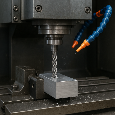
Product Spotlight: PCB CNC Drilling Machine
When you're working with through-hole components, hole accuracy isn't optional—it's essential. That's where our PCB CNC drilling machines step in. These machines are designed to meet the demands of high-precision PCB manufacturing. Whether you're building one prototype or running full-scale production, they deliver the consistency needed to hit your tolerances every single time.
Each machine is equipped with high-speed spindles and motion control systems. That means it doesn't just drill fast—it drills with pinpoint accuracy, even on boards packed with components. This kind of control ensures the finished hole size stays within spec, no matter how many layers or how dense the layout.
They're also smart. The automatic tool change system swaps drill bits on the fly, cutting downtime and keeping production flowing. It's especially useful when switching between different hole sizes or drilling into tough materials like FR-4. Real-time error detection features monitor the drill path and bit condition, catching issues before they turn into scrap. It saves time, material, and stress on the line.
From tight-tolerance vias to oversized mounting holes, the machine handles it all. Here's what sets it apart:
| Feature | Benefit |
| High-speed spindle | Clean cuts through multiple layers |
| Precision motion control | Maintains tight hole size tolerance |
| Auto tool changer | Fast transitions between drill sizes |
| Real-time error detection | Reduces waste, flags tool wear early |
| Multi-board support | Ideal for both prototyping and mass runs |
So when you need reliability, speed, and flawless hole quality—this tool is built to deliver.
Conclusion
Selecting the right PCB hole size for through-hole pins is more than just following numbers—it's about making smart, reliable design choices. From solder strength to manufacturability, every fraction of a millimeter matters. The key is knowing your component specs, applying the right clearance, and following standards like IPC-2221 and IPC-2222. Always build in room for tolerances, plan for plating, and test your design on a prototype before full production. Work closely with your fabricator to ensure each hole performs exactly as needed. For further assistance, welcome to check out our company's supporting products.
FAQs
Q1: Why can't I just match the hole size to the pin size?
No two pins are exactly the same. Tolerances and plating reduce space, so a hole that matches the pin diameter often ends up too tight.
Q2: What's the standard clearance I should use?
Most designs work well with 0.2 mm clearance. It balances easy insertion and proper solder flow without making the hole too large.
Q3: How does copper plating affect the hole size?
Plating adds a thin copper layer inside the hole, which reduces its final diameter. You need to drill slightly larger to get the correct finished size.
Q4: Do square pins need different hole sizes than round pins?
Yes. Use the diagonal of the square pin to calculate the effective diameter, then add clearance—otherwise, the hole will be too small.
Q5: What if the datasheet only gives a one-sided tolerance?
Use the maximum pin size, including the full positive tolerance, when calculating your hole size to ensure a proper fit.


